Type F Flange Insulation Gasket Kits
Product Description
Product Detail
Type F Flange Insulation Gasket Kit Supplier — Raised Face, No Bolt Holes, Bulk & OEM Isolation Sets
No Bolt Holes Is the Feature — Drop-in Geometry for Raised-Face Flanges
The Outside Diameter Does the Centering
Most insulation gaskets are cut with bolt holes. Type F is not. The central gasket is an annular ring with no bolt holes at all. The outside diameter is machined slightly smaller than the inside diameter of the bolt circle. When the flange closes, the gasket self-centers inside the bolt circle — no manual alignment, no bolt-hole lineup, no risk of a sleeve catching on a misaligned gasket edge. That is the Drop-in logic. It is a different geometry, not a cost-reduced Type E.
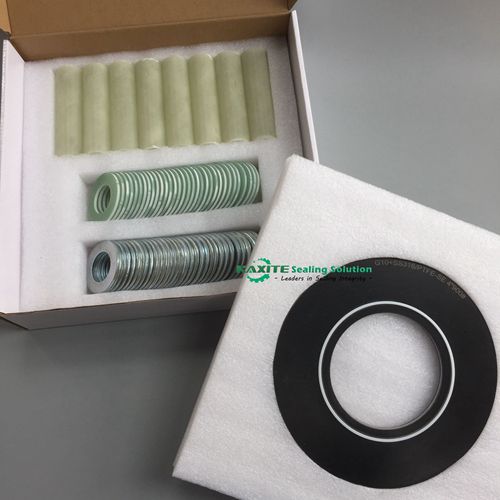
Type F vs Type E vs Type D — Three Geometries, Three Installation Logics
| Dimension | Type F (this page) | Type E | Type D |
|---|---|---|---|
| Flange facing | Raised-face (RF) | Full-face (FF) | RTJ ring groove |
| Bolt holes in central gasket | None | Precision-cut | None |
| Centering mechanism | OD slightly less than bolt circle ID — automatic | Bolt holes sleeve onto bolts | Wedges into groove; groove walls constrain |
| Installation character | Drop-in; no manual centering | Bolt holes must align with bolts | Requires alignment pins and careful seating |
| Typical failure risk | Insufficient tape wrap — external bridging | Bolt-hole contamination or sleeve misalignment | Missing alignment pin or tape wrap |
Why Automatic Centering Matters — Removing a Failure Mode
On a Type E kit, if the bolt holes are slightly misaligned during assembly, the insulating sleeve can catch on the gasket edge and leave a sliver of phenolic exposed — a potential conductive path. Type F removes that failure mode by removing the bolt holes entirely. The gasket positions itself from the outside diameter, and the insulating sleeves only have to isolate the bolts from the flange holes. Fewer alignment interfaces, fewer ways for the kit to short out. For full-face flanges where bolt holes are required, see Type E flange insulation gasket kits.
Carrier Material Choice — Phenolic Is the Default, G10/G11 Go Higher
| Carrier | Dielectric (V/mil) | Compressive (psi) | Max Temp (°C) | Best For | Avoid When |
|---|---|---|---|---|---|
| Plain Phenolic (default) | 500 | 25,000 | +104 | Standard RF flanges, cost-sensitive projects, sealing priority | Service above 104°C |
| Neo-faced Phenolic | 500 | 25,000 | +79 | Rough raised face requiring a soft sealing layer | Service above 79°C |
| G-10 Epoxy Glass | 550 | 50,000 | +138 | Higher temperature, higher bolt load, lower water absorption | Cost-sensitive standard service |
| G-11 Epoxy Glass | 550 | 50,000+ | +176 | Higher temperature ceiling | Cost-sensitive standard service |
The trade-off is temperature and cost. Plain phenolic gives −54°C to +104°C and the lowest material cost. G10 doubles the compressive strength and raises the temperature ceiling to +138°C, at a higher price. For a soft sealing face on a rough raised surface, the neoprene faced phenolic option drops the upper limit to +79°C. For RTJ flanges where the gasket must seat inside a groove, see Type D RTJ insulation kits.
Technical Data — Plain Phenolic Carrier (Type F)
| Dielectric strength | 500 V/mil |
|---|---|
| Compressive strength | 25,000 psi |
| Water absorption | 1.6% |
| Insulation resistance | 40,000 Meg Ohms |
| Flexural strength | 22,500 psi |
| Operating temperature | −54°C to +104°C (−65°F to +220°F) |
| Standard thickness | 1/8″ (3.2 mm) |
| Pressure class | ANSI Class 300 standard; confirm for higher ratings |
Tape Wrap Still Applies — the Exposed Raised Face Is a Short-Circuit Path
Why Tape Wrap Is Not Optional
Type F has no bolt holes, but the raised face is still exposed at the flange OD. Conductive debris — rust scale, water, graphite dust — can bridge that exposed edge. Wrap the assembled flange OD with insulation tape after bolting. This step is specified for a reason; field failures on Type F kits are almost always contamination bridging, not the phenolic itself.
What Drop-in Does Not Remove
Drop-in removes the manual bolt-hole alignment step. It does not remove the need for clean flange faces, correct bolt load and tape wrap. The kit is easier to install, not maintenance-free.
Kit Contents and Factory Traceability
Each Type F kit includes the annular phenolic central gasket, insulating sleeves, insulating washers and steel back-up washers. Kaxite operates an ISO 9001 quality system; kits are supplied with material certificates and dimensional inspection records. Dielectric strength is verified on the central gasket before shipment. Third-party inspection (SGS, BV, Intertek) can be coordinated. For the full range of insulation kit types, see flange insulation gasket kits.
MOQ, Lead Time and OEM Packaging
Standard MOQ is 10 sets; standard lead time is 7–15 days for standard RF kits. Custom carrier materials (G10/G11) and non-standard sizes are quoted separately with confirmed timing. OEM marking and private-label packaging are available. For very critical service beyond the standard phenolic range, see the VCS flange insulation gasket kit.
Buyer FAQ
- Why does Type F have no bolt holes — and how does it center?
- The outside diameter is machined slightly less than the bolt circle inside diameter. When the flange closes, the gasket self-centers inside the bolt circle. No manual alignment is required, and there is no bolt-hole edge for a sleeve to catch on. The Drop-in geometry removes an alignment interface.
- Type F vs Type E — when should I specify the Drop-in geometry?
- Specify Type F when the flange is raised-face and you want Drop-in installation without bolt-hole alignment. Specify Type E when the flange is full-face and the gasket must cover the entire flange OD including the bolt holes. The flange facing determines the type.
- What pressure class and temperature can a Type F phenolic kit handle?
- ANSI Class 300 is the standard pressure reference for a plain phenolic Type F kit. Plain phenolic covers −54°C to +104°C; a neoprene sealing face drops the upper limit to +79°C. For higher temperature, G10 (+138°C) and G11 (+176°C) carriers are available.
- Is tape wrap still required on Type F?
- Yes. Type F has no bolt holes, but the raised face is exposed at the flange OD. Tape wrap after bolting closes that edge against conductive debris. Drop-in removes the alignment step, not the contamination-control step.
- What is the MOQ and lead time for Type F RF kits?
- MOQ is 10 sets for standard RF kits; standard lead time is 7–15 days. G10/G11 carriers and custom sizes are quoted separately with confirmed timing.
- Can you supply Type F in G10 or G11 for higher temperature?
- Yes. G10 raises the temperature ceiling to +138°C and compressive strength to 50,000 psi; G11 raises it further to +176°C. State the service temperature and bolt load at inquiry so the correct carrier is quoted.
Send your RF flange size, pressure class, carrier material (phenolic / G10 / G11) and service temperature. Engineering team confirms the kit construction, MOQ and lead time.
Request Type F Kit Quotation